Friday, July 19, 2013

Whirly-Gig: Charlieplexing and SoftwareServo on ATtiny45

I recently completed a project involving an ATtiny45 and wanted to share it with the world. The idea came from the world of FIRST robotics. At competitions some teams have spinning banners ("whirly-gigs") above their pits to attract scouters, judges, and anyone else who might be interested. I had a friend who saw it and told me to make one for her birthday. Sounds like fun! Let's get started.

Hardware involved:

  • 1: ATtiny45
  • 1: HXT900 Servo (modified)
  • 1: Momentary Switch
  • 1: 10k Potentiometer
  • 1: 5V Voltage Regulator
  • 1: DC Power Jack
  • 1: 2 Way Switch
  • 1: 3 Battery AA Holder
  • 6: 5mm Colored LEDs
  • 3: 270 Ohm resistors
  • Wire
Software Involved
First, the ATtiny core. I have done several posts involving ATtinys in the past. Follow the instructions from the link above to use an ATtiny with the Arduino IDE.

Second, the SoftwareServo Library on the ATtiny. I have already done a post on controlling servos with an ATtiny. Find it HERE. Basically, the regular Servo library will not work because it doesn't have the necessary timer, so SoftwareServo must be used.

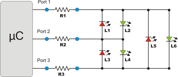
Next we have the Charlieplex Library. It takes care of setting the pins correctly to turn on the LEDs we will be using. I have done a post on this library as well. Find it HERE.

Last we come to my sketch. You can get it HERE. It may be a bit convoluted , so I tried to comment it to be understandable. The essence is this, there are 10 different LED modes that the user switches between by pushing a button. At the same time the servo which has been modified for continuous rotation as discussed HERE is controlled by turning a 10k pot.

I made a nice wooden base for the electronics and mounted the servo on 2 wooden uprights. The sign itself is made of dowel rods and home insulation foam cut into circles. I made it such that an 8.5 x 11 sheet of paper will fit on it when rolled horizontally.

I soldered together all the electronics. I put a 270 Ohm resistor on each LED pin. I also put a 10 uF electrolytic capacitor across the power leads and a diode protecting against unwary users plugging in power backwards, but those probably aren't necessary.

I did run into one problem in the course of this process. The servo would stop working when I set a certain LED pin LOW. I never did get to the bottom of it, but it is discussed in THIS forum thread. I ended up changing the pins I was using, and it solved the problem. I included a diagram of my pinout in the code posted above.

That's about all the details I am going to give you. The whole project took quite a while, and it's a DIY project. I'm not selling kits. If you want, you can view my project photos HERE, and I took a nice video for you to look at. I hope I inspired you to greatness.


-Matthew

Tuesday, July 16, 2013

Deer Defense System: PIR motion sensor

Today I will provide information necessary to build a Deer Defense System (DDS). The specific plans I will be using were leaked from an undisclosed source at the DoD and are highly classified. Continue reading at your own risk.

This summer has been a unique adventure at the family garden. First, for whatever reason our squash have grown huge this year. Second (and more relevant), the deer have been particularly aggressive and determined.

For those of you that may not know, in certain areas of the Southern United States white-tailed deer (Bambi) are quite prolific. What may be less known is that these deer love to eat bean plants and will tolerate eating squash, tomatoes, cucumbers, and anything else you don't particularly want eaten. I can vouch for this from experience. Feast your eyes on the destruction.

Well we explored several more traditional methods of repelling deer. We tried all sorts of smelly concoctions. Some worked until it rained. Planting garlic did not help. Marigolds and mothballs did not help. The .30-06 did not work (We didn't try. Deer are out of season. Babies). They sell motion activated sprinklers that would probably work, but they are $50 a piece. No dice.

Having too much free time, I set about making a motion activated deer scaring device (these plans weren't really stolen from the DoD). Here is an overview.

At the heart of the matter is a Pyroelectric InfraRed  sensor. Mine was purchased from Ebay for $1.98. It does work, but be warned, when I asked for the datasheet they said it was a "trade secret." Right. Several other vendors carry them. For details on how to use a PIR sensor see THIS link. Basically, a pin goes high when it senses motion.


 My sensor had several adjustments on it. I found the picture on the left that tells what everything does. By wiring up an LED as discussed in the link above, I then found the settings that worked best for me.

After getting my motion sensor working I had to decide what brains to put in it. I considered another ATtiny45 , but decided to try something simpler first. I just hooked a transistor to the output of the sensor and used it to turn on a bright LED and sound a buzzer. 


Now the biggest concern I have here is the power consumption. I am powering the entire thing on 3 AA batteries. I read online that most of these PIR sensors use about 1.2 mA while on idle. I need a way to shut it down during the day (deer eat gardens after dark). Basically I want a nightlight circuit. 

I had a photo-resistor, but unfortunately the only transistors I had were NPN. This led me to use THESE plans to turn on the power to the PIR sensor only when it is dark outside. When it is light, it supposedly uses in the realm of .1 mA. With this addition, the DDS should last a month or so depending on how often the alarm goes off. Below is a rough diagram of what I built. The circuitry on the left turns on the power at night. The stuff on the right scares the deer.
The switch is the PIR sensor
I soldered everything together and hot glued it into a nice watertight container. Now it is ready to go. I don't know if it will actually scare off the dear or not. I suspect it will not do too much. Regardless, it was a fun project. I hope you enjoyed it!

-Matthew 


Saturday, July 13, 2013

Charlieplexing on an ATtiny85: 3 pins, 6 LEDs

While exploring the world of ATtinys and Arduinos I came to a problem. I needed to control 4 LEDs with only 3 pins. Well this is a problem. I scurried around trying to conceive a clever way to borrow a pin from another application to no avail.

Having previously encountered multiplexing, I turned to that. There I found my solution. Charlieplexing. According to Wikipedia, Charlieplexing uses the tri-state logic capabilities of microcontrollers to control gobs of LEDs with a few pins. The details of Charlieplexing are a bit confusing. I don't feel fully qualified to explain them, so here are the important things to know.

1) An Arduino pin can be in 3 modes: OUTPUT: HIGH, OUTPUT: LOW, or INPUT. When a pin is set as an input, it is put in a high-impedance state. Outputs are in a low-impedance state. If you have no idea what I'm talking about, see THIS link.

2) LEDs (Light Emitting Diodes) only work in one direction. If you did not know this you may have at some
point wondered why your LED was not working. Don't worry. Ignorance isn't a crime...that I know of.

3) Your Arduino (even your ATtiny) can turn LEDs on and off many more times a second than your eye can see. Think how a video shot at 30 frames per second (NTSC TV) looks. That's 30 Hz. A "normal" Arduino runs at 16 MHz (16000000 Hz). Now granted you can't turn an LED on and off that fast, but you get my point. I will be running the ATtiny at 8MHz. This is the fastest you can run it without external hardware.

All this combined means that I can control 6 LEDs with only 3 pins. Great! Next I searched for a library to take care of all the heavy lifting. Introducing the Charlieplex Library. This library takes care of all the tedious stuff to let us worry about what we want the LEDs to do at the Macro level.

I'm not going to go into the details of how to use the library because the Arduino playground page does a pretty good job. However, for those that are interested HERE is my code. It is a basic modification of the SimpleCharlie example to control 6 LEDs.

To the right is a schematic for how to wire up the LEDs. There are also resources available on Google to help you do that. HERE is one resource on how to draw your own schematic. Video would be rather anticlimactic, and I have already disassembled it. The schematic will have to do.


Hope this works for you. 
-Matthew